Background
The water phase of experiments in the UMD Three Meter Geodynamo was originally intended to be a short-term mechanical testing shakedown prior to sodium fill and magnetohydrodynamic experiments. However, the initial hydrodynamic results were so unexpected and interesting that we decided to thoroughly characterize the water system behavior before moving on to sodium. My Ph.D. thesis and many other publications are concerned almost entirely with results from water experiments.
However, the project design and budget were not focused on hydrodynamic instrumentation. Some instrumentation, like the inner sphere torque sensor, pressure sensors, and ultrasound velocimetry instrumentation were dual-purpose with planned sodium experiments, and were justified major capital expenses. For water-specific instrumentation, we had to improvise.
The circuit on this page estimates the local fluid shear stress at the wall using a thermal technique with a long history in experimental fluid dynamics. The heat energy lost from the surface of a hot element exposed to the flow is a function of the flow past it. It's possible to feed the heated element with constant current or power and measure its instantaneous resistance to infer its temperature, but interpreting this result requires knowledge of the thermal time constants of the sensor and is slower to respond to fluctuations becasue of the sensor's thermal mass. The circuit here implements a superior technique and uses feedback to keep the sensor's temperature constant. The electrical power required to do this is related in a straightforward way to the fluid shear stress at the wall.
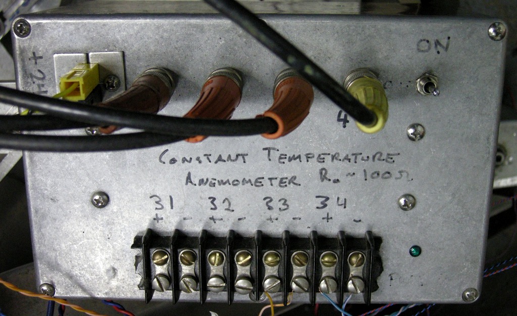
Constant temperature anemometer enclosure
Circuit Design
Typically, these hot wire or hot film systems use a tiny quartz-coated wire or a custom-designed thin film resistor on an insulating substrate as the sensing element. However, I wanted to observe spatial gradients of wall shear stress and cross-correlations between fluctuations from several sensors, and planned a system with at least four sensors. Commercial sensors are fragile and expensive, and a turn-key system to do what I wanted would be around $30,000, far beyond the justifiable budget for this project. Here, I developed a system using a low cost (~$2.50/ea at the time of this writing) platinum thermistor as the sensing element. The circuit is shown in the schematic below.
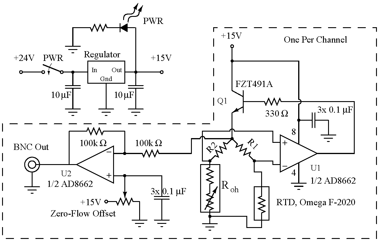
Schematic – [PDF Version]
The sensing thermistor is inserted into one leg of a Wheatstone bridge, and an op-amp feedback circuit modulates the electrical power flowing through the bridge to keep it balanced. The bridge is balanced at only one value of the thermistor's resistance, corresponding to a particular sensor temperature.
The device I fabricated had four CTA channels driving a square array of four Omega F-2020 100 ohm platinum thermistors. The array is depicted below, mounted on one of the instrumentation port inserts that penetrates the top lid of the experiment.
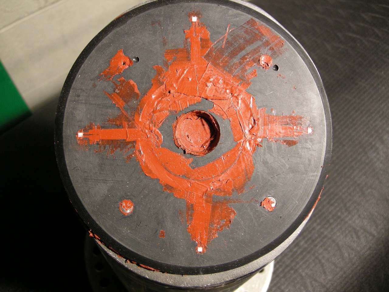
Thermistor array
Measurements
The sensors were not calibrated in absolute wall shear stress units. Instead, their response was measured as a function of inner sphere torque with the outer sphere stationary. I assumed that the large-scale spatial pattern of wall shear stress on the boundaries of a highly turbulent flow will not change appreciably with inner sphere speed, so that the local wall shear stress should be proportional to the torque demanded by the flow.
When the outer sphere rotates, the spatial pattern of shear stress on the outer boundary changes substantially. All results with overall rotation were normalized by the expected value with the outer sphere stationary. The image below shows the normalized wall shear stress τw correlated with slow torque and velocity fluctuations occuring in an interesting fully-turbulent bi-stable flow state.
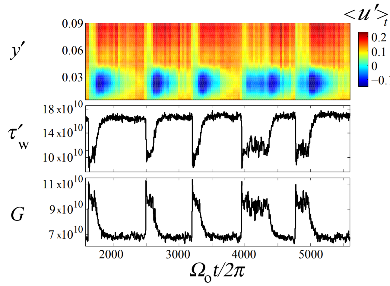
Experimental results
Reproducing the Circuit
I fabricated my own printed circuit boards for the four-channel device depicted here using iron-on toner transfer. The circuit is packaged in a shielded box. The entire system could be easily miniaturized, but this wasn't necessary in my application.
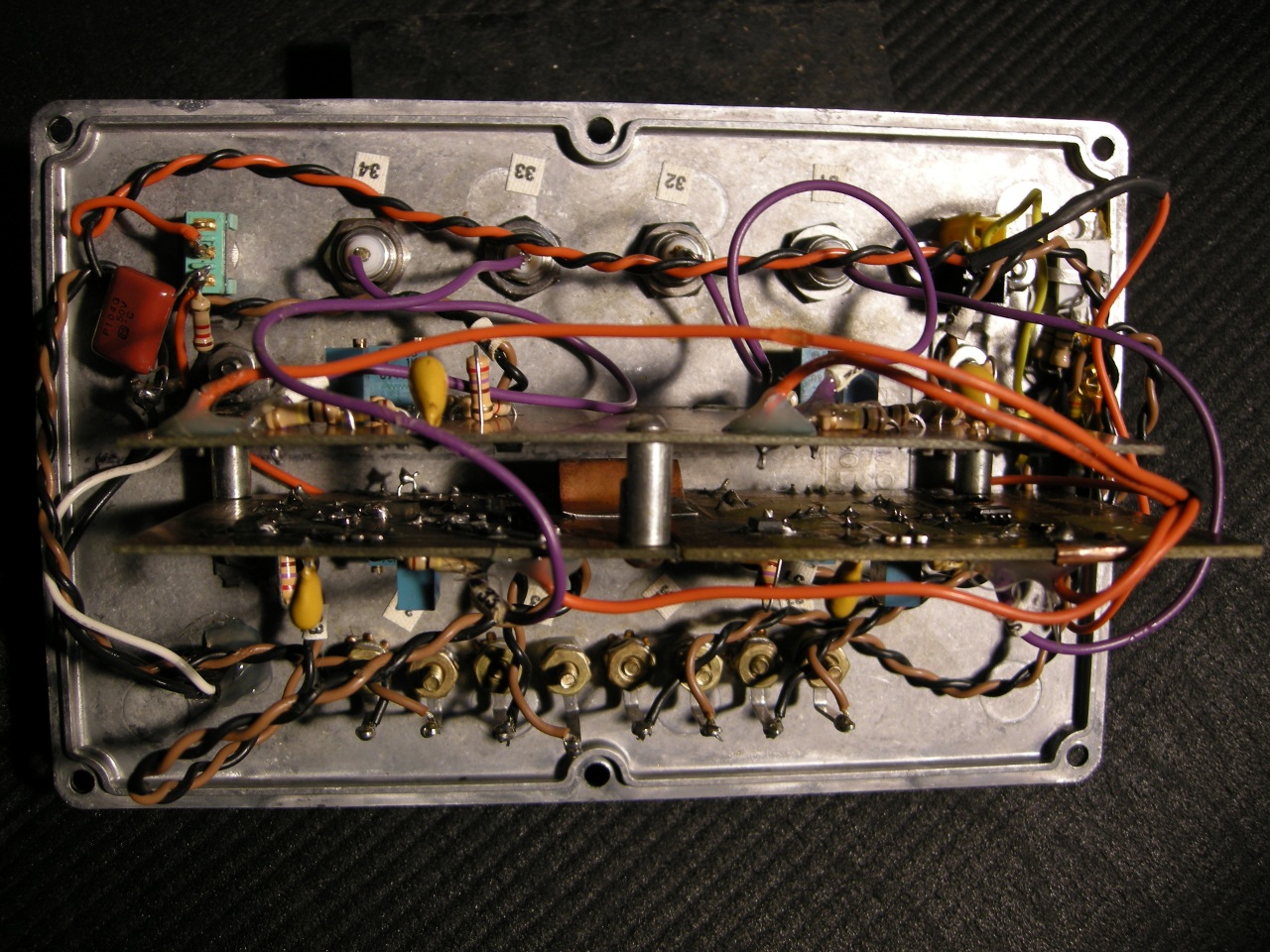
Interior view
If you're interested in building this design for yourself, you can download the PCB layout and parts placement. This thermal anemometer design is hereby released subject to the Solderpad 2.0 License, which is a permissive hardware license allowing pretty much any use.
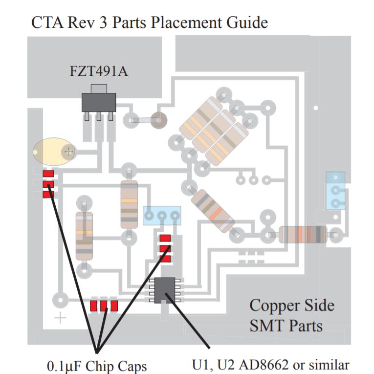
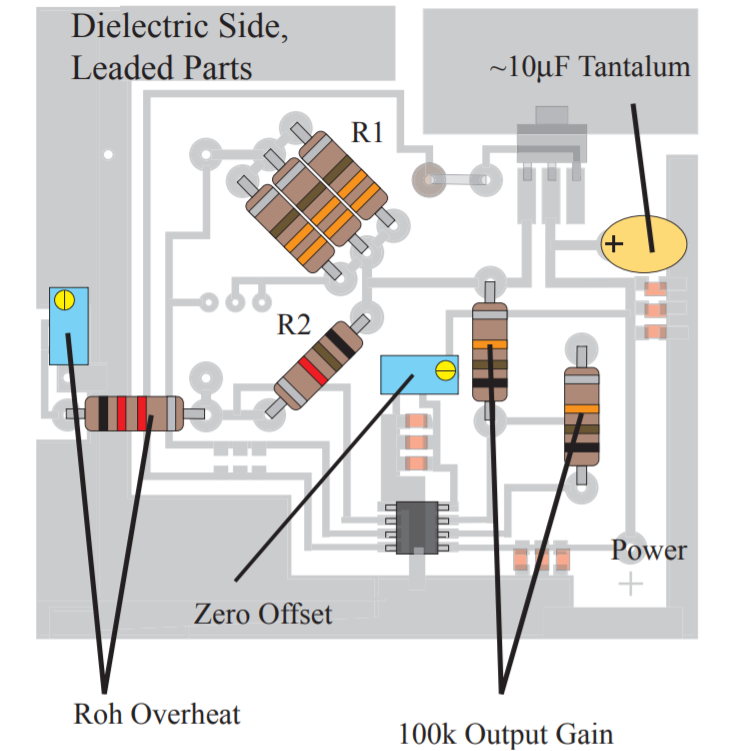
Parts placement [PDF with PCB Layouts]
The dynamic response of this circuit is much faster in water than it is in air, but the circuit also works well in air, and the sensor can be used as a free-stream velocity meter by mounting it in the clear away from walls. It would be easily adapted as an air velocity sensor or fluid flow meter for other applications. Give it a try.