Background
The project on this page describes a simple but very successful circuit to enable ultrasound velocimetry measurements in the rotating UMD Three Meter Geodynamo Experiment. An ultrasound velocity profiler (UVP) transmits ultrasound pulses from a small transducer in contact with a fluid and then listens for returned echoes from seed particles moving in the flow. The timing and phase of the returned echoes are processed into a spatial profile of fluid flow velocity along the beam direction. Typical frequencies are in the 500kHz - 20MHz range depending on desired seed particle size and fluid characteristics.
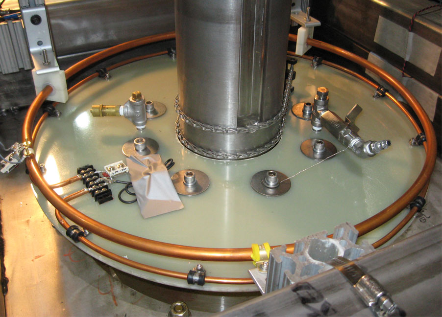
Installed resonant inductive coupler
The Problem
At the time, we had an 1980s vintage ultrasound Doppler instrument that was in perfect working order but required the user to control it from the front panel (monochrome CRT, DR-DOS running on an i386, but still plugging along!). Newer units run headless over a network connection and can easily be mounted remotely, but in this case, a rotary electrical joint in the analog ultrasound path was the only feasible way to mount the ultrasound transducer in the rotating frame of the outer sphere. The ultrasound echoes are weak, and I expected that mechanical slip rings would introduce too much noise. Suitable slip rings of the large size required didn't really fit the budget we had at the time.
The Solution
Instead of a mechanical slip ring, I built the non-contact signal coupler depicted above. A schematic is shown below. A pair of resonant LC circuits tuned to the ultrasound operating frequency are coupled to each other via their magnetic fields. The resonance greatly enhances their mutual coupling, and for rings that are close-spaced like this, the efficiency of coupling is probably 95%. An air core transformer without the resonant coupling would not achieve anything close to this. The resulting performance of the device pictured here was indistinguishable from a direct cable connection, and was implemented on several other rotating experiments in the lab with great results.
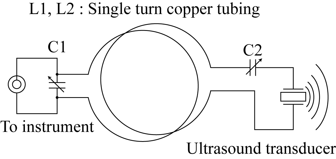
Schematic
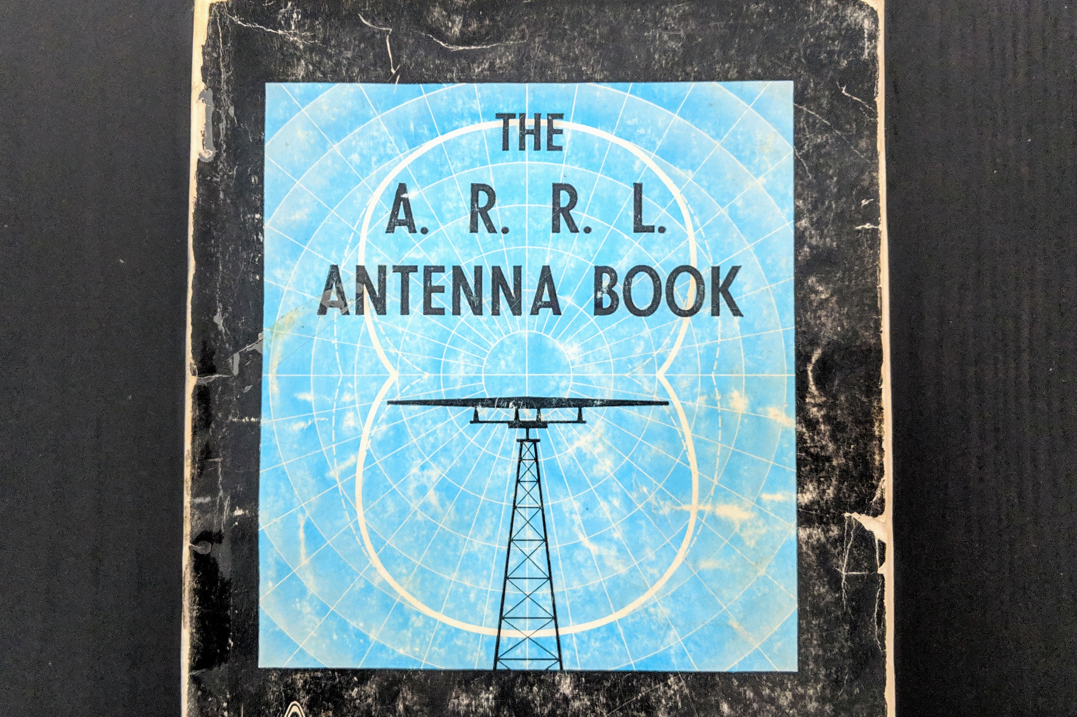
The idea is similar to recent designs for wireless power transfer circuits, but my inspiration was much older. From the ARRL Antenna Book, Tenth Edition, 1964, Ch 3.:
It is possible to match impedances by using inductively-coupled resonant circuits connected to the line and antenna. Although such a method has little application in most antenna systems, it is quite useful when a line is to be matched to a rotatable beam antenna. In such a case it avoids the necessity for any direct metallic connection between the antenna and line, and so allows continuous rotation without slip rings or other forms of contactor.The technique is a really effective way to couple energy across a rotating joint with no contact. But use some care if you implement it yourself in a band where you're not licensed to emit modulated radio signals. Check to make sure you're within FCC limits for unintentional radiation for the frequency you're operating in. This is regulated under 47 CFR 15 in the United States. I used NEC-2 modeling software to check this out for the transmitted ultrasound pulses in my case.
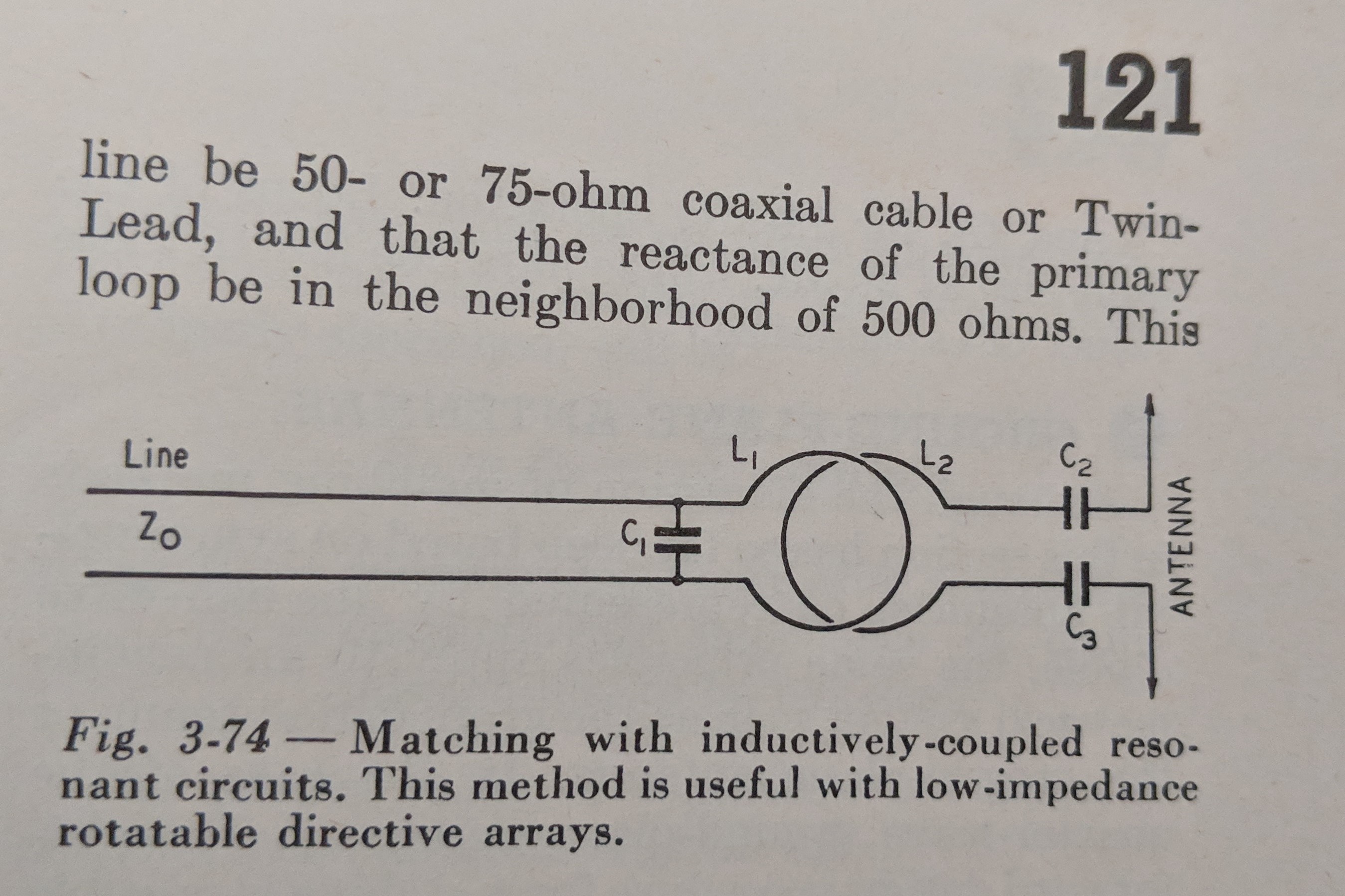
Inductive coupling technique used to match to rotary antennas, 1964
The strong coupling between the two rings means that not much energy escapes as radiation, but the regulated limits on field strength are quite weak, so it's worth looking into, especially if the coupled signal is strong. The original antenna application described above doesn't have to consider these constraints, as all of the coupled power will be radiated anyway.